


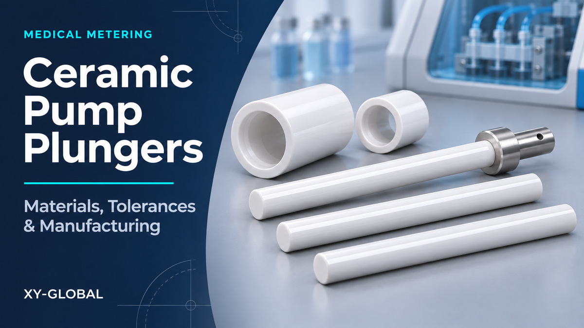
Ceramic pump plungers are used in fluid-handling applications where wear, chemical exposure and dimensional consistency influence pump performance. For medical metering pumps and diagnostic instruments, selecting the ceramic is only one part of the specification. The plunger must also work with its cylinder, seal, drive connection and cleaning process.
A component can meet its diameter tolerance and still produce unacceptable leakage, friction or dosing variation after assembly. The most useful purchasing specification therefore connects material and manufacturing requirements to the operating conditions of the complete pump.
This guide focuses on custom ceramic plungers for equipment manufacturers and pump-module suppliers, particularly those developing medical and laboratory fluid-handling systems.

Define the Pump Architecture First
Before selecting a material or tolerance, identify how the pump displaces and seals the fluid. Suppliers sometimes use “piston” and “plunger” differently in product descriptions. A sectional drawing is more informative than the component name alone.
In a conventional plunger arrangement, the moving rod passes through a stationary seal. Its working surface must be compatible with that seal and remain aligned throughout the stroke. In a close-clearance ceramic piston-and-cylinder assembly, the relationship between the two precision surfaces becomes central to leakage and movement.
These architectures require different specifications. A seal supplier’s surface recommendations should not automatically become the requirements for a ceramic-to-ceramic clearance fit.
Also distinguish between solid ceramic parts, ceramic sleeves fitted to a metal core, and ceramic-coated metal plungers. They have different interfaces, failure modes and manufacturing routes. A drawing that simply states “ceramic plunger” leaves too much open to interpretation.
At the start of a sourcing project, define:
- The sealing arrangement and mating components.
- The working diameter, stroke and engagement length.
- The fluid-contact surfaces and operating orientation.
- The connection between the ceramic part and the drive mechanism.
- Whether the requirement is for a standalone part, a matched pair or an assembled module.
Map the Actual Fluid Exposure
Medical equipment is not a single operating environment. A plunger handling diagnostic reagents may face different conditions from one used in a patient-connected fluid path. Ceramic metering components are commercially used in diagnostic and medical equipment, but suitability must be established for the particular application.
Build an exposure list covering the process fluid, cleaning agents, rinse fluids and any applicable disinfection or sterilization cycle. Record concentrations, temperatures and exposure times rather than describing the environment only as “chemical resistant” or “medical grade.”
Include conditions outside normal operation. Storage with residual liquid, repeated starts, dried reagent deposits and accidental particle entry can reveal problems that a short test with clean water does not reproduce.
For analytical instruments, agree on acceptance criteria for carryover and contamination where relevant. A smooth-looking ceramic surface does not, by itself, demonstrate that an assembled fluid path can be cleaned sufficiently for the intended assay.
Select Alumina or Zirconia Grades
Alumina and zirconia are established candidates for precision ceramic pump components. The selection should identify a specific grade and supplier specification, rather than rely on the generic material name.
| Material | Reasons to Evaluate It | Questions Before Approval |
|---|---|---|
| Alumina | Hardness, wear resistance and established use in precision fluid-handling components. | What purity and composition are required? Are the grade, surface condition and mating materials suitable for the actual fluids? |
| Zirconia | Higher fracture toughness than many conventional alumina grades, which may help where mechanical loading is a concern. | Which stabilized grade is specified? What evidence supports its performance under the proposed temperature, moisture and cleaning conditions? |
Higher toughness does not eliminate brittle fracture, and higher alumina purity does not automatically solve every compatibility problem. Compare grade-specific data and evaluate the finished component in its intended assembly.
Material substitution should trigger an engineering review. A change in ceramic formulation can affect finishing behavior, thermal expansion and the interaction with the mating cylinder or seal.

Connect Dimensions to Metering Performance
For a simple cylindrical displacement element, the ideal displaced volume is:
V = πD²S / 4
Here, D is the effective displacement diameter and S is the stroke. This relationship assumes the relevant cylindrical area moves through the stated stroke. It does not include leakage, trapped gas, valve behavior or fluid compressibility.
Illustrative calculation: a 4 mm effective diameter moving through a 5 mm stroke gives a theoretical displacement of approximately 62.8 mm³, or 62.8 µL. These dimensions are an example, not a recommended medical pump design.
For small dimensional changes, the approximate geometric relationship is:
ΔV / V ≈ 2ΔD / D + ΔS / S
This helps explain why both diameter and stroke deserve attention. However, a geometric calculation cannot establish actual dosing accuracy. The assembled pump must be tested across its intended fluid, pressure, temperature and operating range.
Separate systematic delivery error from cycle-to-cycle variation when defining acceptance criteria. The causes and corrective actions may differ, even when both appear as an incorrect delivered volume.
Specify Fit Beyond Diameter Tolerance
For a close-clearance assembly, calculate the clearance from both components. The plunger drawing alone cannot establish the final fit.
Minimum diametral clearance = minimum bore diameter − maximum plunger diameter.
Maximum diametral clearance = maximum bore diameter − minimum plunger diameter.
Illustrative tolerance stack: suppose the bore is specified as 4.006–4.008 mm and the plunger as 4.000–4.002 mm. The resulting diametral clearance is 4–8 µm. For ideal concentric cylinders, the corresponding radial gap is 2–4 µm. This example demonstrates the calculation only; it is not a recommended running clearance.
The appropriate fit depends on fluid viscosity, pressure differential, engagement length, temperature, particle conditions and acceptable leakage. Making the clearance smaller can introduce other problems, including sensitivity to contamination and geometric variation.
Consider these characteristics alongside size:
- Roundness: variation around individual cross-sections.
- Cylindricity: form over the working cylindrical surface.
- Axis relationship: alignment between the working surface and mounting features.
- Shoulder geometry: the seating surfaces that establish the installed position.
For matched pairs, specify pair identification and replacement rules. If individual parts must be interchangeable, the manufacturing and inspection plan must demonstrate that requirement without relying on selective pairing.
Define the Working Surface Requirements
“Mirror polished” is a visual description, not a complete engineering specification. Define the functional surface, the required texture parameters and how they will be measured.
Ra can be useful, but it does not describe every feature relevant to sealing or sliding. Local scratches, pits, waviness and edge damage may need separate acceptance criteria. Identify the working length so that the finishing and inspection scope is unambiguous.
A practical drawing note should state the measurement direction and evaluation conditions agreed with the inspection supplier. For narrow or difficult-to-access surfaces, confirm that the proposed method can actually measure the specified feature.
When an elastomeric or polymer seal is used, obtain the seal supplier’s recommendations for the mating surface. Do not assume that the lowest achievable roughness produces the best result in every sealing arrangement.
Specify entry chamfers and edge treatment as functional features. An uncontrolled sharp edge or chipped lead-in can damage a seal during assembly even when the main working surface meets its roughness requirement.

Plan Machining and Finishing Together
Precision ceramic pump plungers are not necessarily produced by machining a fully sintered blank through one conventional CNC operation. A suitable route may combine blank forming, green or presintered machining, sintering and hard finishing.
After sintering, diamond grinding can establish critical dimensions and geometry. Lapping, honing or polishing may be appropriate for particular mating surfaces. Controlled wet grinding is an established ceramic finishing method; a blanket requirement to avoid liquid coolant is not appropriate.
The supplier should identify which features are finished after sintering and how machining allowance is established. Shrinkage compensation depends on the material and manufacturing process, rather than one universal percentage.
During the design review, ask which requirements drive extra setups, special tooling or inspection time. Tightening every dimension equally can increase cost without improving the working interface. Apply the most demanding requirements to the features that control displacement, sealing and alignment.
Protect the Ceramic During Assembly
The drive connection deserves the same attention as the fluid-contact surface. A misaligned actuator, uneven clamping surface or poorly supported shoulder can introduce bending or concentrated contact loads.
Review the assembled load path and identify where force enters the ceramic. Give the supplier the mating hardware geometry, not just the ceramic drawing. This helps expose difficult transitions, unsupported sections and assembly access problems before prototypes are made.
For a bonded metal adapter, define the joint geometry, adhesive exposure and inspection requirements. If a sleeve or mechanical retention feature is used, evaluate the assembly stresses and thermal behavior of the complete connection.
Assembly instructions should identify handling surfaces and prohibited contact areas. Protective packaging should prevent the finished working surface from rubbing against other components during transport.
Separate Inspection From Functional Validation
Part inspection and pump validation answer different questions. Dimensional inspection verifies specified characteristics of the component. Functional testing establishes whether the assembled system delivers the required performance.
| Verification Level | Items to Define |
|---|---|
| Material and traceability | Grade identification, material documentation, lot traceability and approved substitutions. |
| Component inspection | Working diameter, geometric form, mounting features, surface texture and agreed defect criteria. |
| Assembly verification | Movement, alignment, retention and leakage under specified conditions. |
| Pump validation | Delivered volume, repeatability, pressure behavior, cleaning performance and endurance. |
Agree on measurement uncertainty, inspection temperature and sampling before production. A measurement method must be suitable for the tolerance and geometry; the presence of a CMM alone does not establish that every micron-level feature can be verified adequately.
Where direct or indirect body contact makes biological evaluation relevant, material identity alone is insufficient. FDA guidance considers the medical device in its final finished form, including sterilization when applicable. The device manufacturer should determine the evaluation scope for the actual contact conditions.
For a diagnostic reagent path without patient contact, establish the applicable analytical and cleanliness requirements rather than assuming every medical application needs the same biological tests.
Prepare a Useful Quotation Package
A complete request for quotation helps suppliers identify technical uncertainties before those uncertainties become price differences or prototype delays.
- Drawings: a dimensioned 2D drawing and a 3D model where useful, with revision identification.
- Material: the required grade, documentation and substitution policy.
- Functional geometry: working diameter, stroke, contact length, mounting features and edge requirements.
- Mating parts: cylinder, seal and adapter details, including clearance or pairing requirements.
- Operating conditions: fluid composition, temperature, pressure, speed and duty cycle.
- Cleaning exposure: agents, concentrations, temperatures and cycle durations.
- Acceptance criteria: inspection requirements, defect limits and functional test responsibilities.
- Supply scope: individual components, matched sets or assemblies, plus prototype and production quantities.
Ask the supplier to identify proposed exceptions separately from the quoted price. If an alternative tolerance, grade or finishing route is suggested, record it explicitly so that quotations can be compared on the same basis.
FAQ
Are ceramic pump plungers always solid ceramic?
No. Available constructions include solid ceramic parts, ceramic sleeves and ceramic-coated metal plungers. Specify the construction because the interfaces, inspection needs and failure mechanisms differ.
Is alumina or zirconia better?
Neither is universally better. Compare specific grades against chemical exposure, mechanical loading, mating materials and processing requirements. Confirm the selection through relevant component and assembly testing.
What tolerance should a ceramic plunger have?
There is no universal tolerance. Start with the required displacement and sealing behavior, then allocate size and geometry requirements across the plunger, mating cylinder and mounting features.
Can CNC machining produce the final surface?
The answer depends on the material, process and specified surface. Precision ceramic components may require post-sinter grinding and additional finishing. Confirm the complete route instead of relying on the CNC label alone.
Does a smooth plunger guarantee accurate dosing?
No. Dosing also depends on stroke control, leakage, valves, trapped gas, fluid properties and assembly behavior. A surface inspection report does not replace testing of the assembled pump.
Discuss Your Ceramic Plunger Requirements
For a custom ceramic pump plunger project, send XY-GLOBAL the component drawing, mating-part information, proposed material and operating conditions. Include the required inspection records and clarify whether you need standalone parts or matched components.
Use the ceramic CNC machining services page to start a discussion about manufacturing feasibility. Confirm the material-specific process, achievable tolerances, finishing scope and delivery requirements during the project review.
Technical References
The following resources provide background on ceramic pump applications, materials, manufacturing and medical-device evaluation. Their product specifications describe the respective manufacturers’ offerings and are not XY-GLOBAL capability guarantees.
- Niimi Ceramics: Ceramic Pistons for Metering Pumps — examples of ceramic metering components for medical and diagnostic applications.
- CeramTec: Ceramic Components for Pumps, Valves and Seals — application and material-selection context.
- CoorsTek: Alumina — background on application-specific alumina compositions.
- CoorsTek: Zirconia — background on zirconia material families and mechanical applications.
- Technical Ceramics: Manufacturing and Design Handbook — background on sintering, hard finishing and ceramic design.
- FDA: Basics of Biocompatibility — evaluation considerations for the finished medical device.

Aktie:
Alumina vs. Zirconia Ceramics: Properties, Machining, Applications, and Material Selection for Custom Precision Parts