


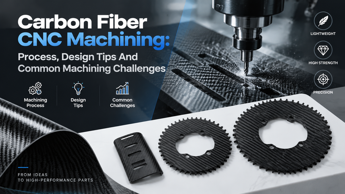
Carbon fiber parts are lightweight, stiff, and increasingly common in aerospace, robotics, automotive, and high-performance equipment.
But machining them is not as straightforward as machining aluminum.
The most common problems are usually not part geometry itself. They are delamination, frayed edges, rapid tool wear, heat buildup, and fine conductive carbon dust. A part may look simple on the drawing, but poor tooling or cutting strategy can quickly damage the laminate.
The good news is that these challenges can be controlled by carbon fiber CNC machining.

What Is Carbon Fiber?
Carbon fiber (CF) is a high-strength fiber made mostly of carbon, typically with a carbon content above 95%. It is lightweight, strong, and stiff, but individual carbon fibers are rarely used alone.
In most engineering parts, carbon fibers are combined with a resin and arranged in layers to form carbon fiber reinforced polymer (CFRP). The fibers provide strength and stiffness, while the resin holds them together and helps maintain the shape of the part.
| Property | Typical Value |
| Carbon Content | >95% |
| Fiber Diameter | Around 5–10 μm |
| Density | Approx. 1.5–2.0 g/cm³ |
| Tensile Strength | Approx. 2–7 GPa |
| Tensile Modulus | Approx. 200–700 GPa |
| Strength Comparison | Can exceed 4× the tensile strength of common aluminum alloys |
| Thermal Expansion | Low and anisotropic |
| Corrosion Resistance | High |
| Electrical Conductivity | Conductive |
| Material Behavior | Anisotropic; properties vary with fiber direction |
| Key Mechanical Characteristic | High specific strength and specific modulus |
Why Machining Carbon Fiber Is Different From Machining Metal
Carbon fiber composites are not isotropic materials like most common metals.
Their properties depend heavily on:
-
Fiber orientation
-
Number of laminate layers
-
Layup sequence
-
Fiber type
-
Resin system
-
Part thickness
A cutting tool may therefore behave differently when moving across different fiber directions within the same part.
This is one reason why simply using the same machining approach as aluminum often causes problems.

Carbon Fiber Is Highly Abrasive
Carbon fibers can wear cutting edges surprisingly quickly.
A tool may still look usable but already be producing poorer edge quality or oversized holes.
As tool wear increases, cutting forces can change and defects such as fiber pull-out or fraying become more likely.
For repeat production, tool condition is therefore more than a maintenance issue.
It becomes part of dimensional control.
Delamination Can Occur Around Machined Features
Delamination happens when layers of the composite separate.
It is one of the most common concerns when machining carbon fiber composites, especially during drilling and edge machining.
Drilled holes are particularly sensitive.
The drill applies force through the laminate, and the exit side of the hole can experience breakout or separation if the tool, support, or process is not suitable.
You may still get a hole.
It just may not be the hole you wanted.
Carbon Fibers Can Pull Out Instead Of Cutting Cleanly
A dull or unsuitable cutting tool may push or tear fibers instead of cutting them cleanly.
This can leave:
-
Frayed edges
-
Loose fibers
-
Rough surfaces
-
Fiber pull-out
-
Chipped laminate edges
For purely cosmetic edges, this may be manageable.
For assembly interfaces or locating features, it becomes much more important.
Heat Needs To Be Controlled
Carbon fiber itself tolerates high temperatures well, but remember that a CFRP component is not made from carbon fiber alone.
It also contains a polymer matrix.
Excessive local machining heat can affect that resin, particularly around the cutting zone.
This is why aggressive engagement, poor tool condition, or unsuitable cutting parameters can cause more than simple tool wear.
Carbon Dust Needs Special Attention
Machining CFRP generates very fine dust.
That dust should not be treated like ordinary aluminum chips.
Besides the obvious housekeeping and exposure concerns, carbon dust is electrically conductive. It should be kept away from sensitive machine electronics and electrical systems.
Proper extraction and machine protection are therefore part of a serious carbon fiber machining process.
Not the most exciting part of CNC machining, perhaps. But definitely not something to ignore.
Common CNC Machining Methods For Carbon Fiber
Different CFRP parts need different machining operations.
There is no single “best” carbon fiber machining process. It depends on what the finished part actually needs.
CNC Milling
Milling carbon fiber is useful for parts requiring complex profiles, pockets, slots, local thickness changes, precision edges, and assembly features.
Tool geometry and cutting direction have a major influence on edge quality.
Unlike machining aluminum, simply increasing spindle speed or reducing feed does not automatically solve the problem.
The correct approach depends on the tool diameter, laminate structure, material thickness, engagement, and required edge condition.
CNC Routing
CNC routing works well for larger carbon fiber sheets and panels. It's often used to cut outer profiles, openings, and other 2D features.
The bigger issue here is usually supported. Thin CFRP sheets can vibrate or lift during cutting. Once that happens, frayed edges and delamination become much more likely.
A stable setup makes a big difference.
CNC Drilling
Drilling carbon fiber sounds easy. Getting a clean, accurate hole is another story.
The trouble often shows up at the hole exit. Delamination, fiber breakout, rough edges, and dimensional changes can all happen if the tool or setup isn't right.
Sharp tools and good backing support help. So does choosing the right drill geometry.
For mounting or locating holes, it's also worth looking beyond the diameter. Hole position and edge condition can be just as important, especially when the part needs to fit another component.
CNC Turning
CNC turning is less common for carbon fiber, but it still has its place.
You'll mainly see it on round parts such as carbon fiber tubes, sleeves, and other cylindrical components. Facing, trimming the ends, or machining an outside diameter are typical examples.
The challenge is familiar: carbon fiber is abrasive. Tools wear quickly, and a worn cutting edge can leave fibers torn instead of cleanly cut.
So while turning CFRP is possible, good tooling and process control still matter.
CNC Waterjet
Waterjet cutting is another option for carbon fiber, especially for flat sheets and panels. It uses a high-pressure water stream with abrasive particles to cut through the material without direct tool contact.
The biggest advantage is simple: there's very little heat involved. That helps avoid the heat-affected areas or resin damage that can come with some thermal cutting processes.

Choosing Tools For Carbon Fiber CNC Machining
Tool selection matters a lot with CFRP.
Standard cutting tools may work for occasional machining, but they can wear quickly when used repeatedly on abrasive carbon fiber laminates.
Common tool options include:
Carbide Tools
Carbide is widely used for machining composite materials.
It can offer a practical balance between tool cost and performance, particularly for prototypes and lower production quantities.
Diamond-Coated Tools
Diamond coatings can provide much better wear resistance when machining abrasive CFRP materials.
They are often worth considering when tool life and consistent edge quality become more important.
PCD Tools
Polycrystalline diamond tools can be suitable for demanding or repeat-production composite machining.
The initial tooling cost is higher, so the decision usually depends on volume, geometry, and required tool life.
Composite-Specific Routers And Drills
Compression-style cutters and composite-specific drill geometries can help control fiber breakout and delamination.
But there is no magic cutter.
The tool still needs to match the laminate, operation, and required features.
How Fiber Orientation Affects Carbon Fiber Machining
Carbon fiber doesn't cut the same way in every direction. A CFRP laminate may have fibers running at different angles, such as:
-
0°
-
45°
-
90°
-
A combination of different orientations
As the tool moves around the part, it meets these fibers at different angles. That's why one edge can come out clean while another shows fraying or fiber pull-out—even with the same tool and cutting parameters.
For better edge quality, fiber direction, cutting direction, and toolpath should be considered together. CFRP can't simply be treated like a uniform piece of metal.
Common Carbon Fiber Machining Defects
Most carbon fiber machining problems are predictable.
The useful question is not whether defects exist. It is what is causing them.
| Machining Defect | Possible Cause | Typical Response |
| Delamination | Excessive cutting or axial force | Review tool geometry, support and cutting strategy |
| Fiber Pull-Out | Dull tool or unfavorable fiber orientation | Use sharp composite tooling and adjust toolpath |
| Frayed Edges | Poor support or unsuitable cutting direction | Improve workholding and edge support |
| Edge Chipping | Vibration or aggressive engagement | Improve rigidity and reduce cutting load |
| Resin Damage | Excessive local heat | Improve tool condition and cutting strategy |
| Oversized Holes | Tool wear or unstable drilling | Monitor tool wear and inspect critical holes |
| Dimensional Drift | Tool wear, movement or laminate variation | Control setup and inspect CTQ dimensions |
Changing the CNC program is not always the answer.
Sometimes the problem begins with the tool. Sometimes with the fixture. And sometimes with the design itself.
Design Considerations For CNC Machined Carbon Fiber Parts
This is where a lot of projects can be improved before machining begins.
A small DFM change may make a part easier to machine, easier to inspect, and more reliable in assembly.
Give Critical Holes Enough Edge Support
Placing a fastener hole very close to the edge of a laminate can increase the risk of local damage.
How much edge distance is needed?
There is no useful universal number.
It depends on:
-
Hole diameter
-
Laminate construction
-
Fiber orientation
-
Fastener load
-
Local reinforcement
-
Application requirements
For critical fastener interfaces, the laminate and mechanical load should be reviewed together.
Metal design rules should not automatically be copied into CFRP.
Avoid Very Thin Unsupported Features
Carbon fiber has an excellent strength-to-weight ratio.
That does not mean every thin machined feature is automatically a good design.
Very narrow bridges, thin tabs, and unsupported edges may be more sensitive to:
-
Vibration
-
Fiber breakout
-
Handling damage
-
Local delamination
If the feature has no functional reason to be extremely thin, increasing local support can often make production easier.
Think About Hole Entry And Exit
A hole is not just a diameter callout.
The way a drill enters and exits the laminate matters.
Backing support, sacrificial material, drilling direction, and tool geometry can all influence exit quality.
This becomes particularly important when both sides of the component are visible or when a hole forms part of a critical joint.
Use Practical Internal Radii
CNC cutting tools create internal radii naturally.
Trying to design extremely sharp internal corners usually creates extra manufacturing effort without adding much value.
There is another reason to avoid them.
Sharp internal geometry can create local stress concentration.
If the assembly allows it, practical corner radii are usually a better choice.
Holes and Inserts
Carbon fiber parts often need holes for bolts, locating pins, or metal inserts. Unlike metal parts, threads should not simply be cut directly into CFRP without considering the load and laminate structure.
For critical connections, metal inserts or bushings may be a better option. Hole size, position, edge distance, and local support should all be considered before machining.
Tolerances In Carbon Fiber CNC Machining
There is no single tolerance that applies to every CFRP component. Achievable accuracy depends on:
-
Laminate construction
-
Material thickness
-
Part geometry
-
Feature type
-
Tool condition
-
Fixturing
-
Inspection method
More importantly, every dimension does not need the same tolerance.
This is where a good tolerance strategy can save a lot of unnecessary manufacturing cost.
Tighter control should normally be focused on functional features such as mounting holes, locating holes, datum features, mating interfaces, and assembly dimensions.
Non-critical outer profiles can often use more practical tolerances.
In other words, do not make the whole drawing difficult just because two dimensions actually matter.
Workholding Carbon Fiber Parts
Stable workholding is important with any CNC machining process.
For thin carbon fiber laminates, it becomes even more important. Common approaches can include:
-
Vacuum fixtures
-
Mechanical clamps
-
Dedicated fixtures
-
Sacrificial backing plates
The objective is straightforward:
Keep the part flat and stable without creating local damage.
Poor support can cause vibration, movement, and breakout near edges or holes.
For prototypes, flexible fixturing may make sense.
For repeat production, a dedicated fixture can improve both cycle time and consistency.
Inspecting CNC Machined Carbon Fiber Parts
Machining the part is only half the job.
You still need to know whether the finished component meets the drawing.
For carbon fiber parts, inspection should usually look at both dimensions and laminate condition.
Dimensional Inspection
Depending on the feature, inspection may include:
-
Hole diameter
-
Hole position
-
Overall dimensions
-
Profile dimensions
-
Datum relationships
-
Mating interfaces
CMM or vision measurement can be useful depending on part geometry and inspection requirements.
Visual Inspection
Not every CFRP defect shows up as a dimensional problem.
Visual inspection can help identify:
-
Delamination
-
Frayed fibers
-
Edge chipping
-
Fiber breakout
-
Resin damage
-
Surface scratches
For a functional component, both sides matter.
A hole can measure correctly and still have unacceptable breakout around its exit.
First Article Inspection
For new designs or parts with critical-to-quality features, first article inspection can help verify the machining process before moving into repeat production.
This is particularly useful when the component includes several assembly interfaces.
Where CNC Machined Carbon Fiber Parts Are Used
Carbon fiber components are used where weight, stiffness, and mechanical performance matter.
Typical applications include:
Aerospace And UAVs
Brackets, structural plates, payload components, equipment mounts, and lightweight assemblies.
Robotics
Robot structures, arms, frames, end-effector components, and lightweight moving assemblies.
Automotive
Motorsport components, structural panels, brackets, fixtures, and lightweight vehicle parts.
Industrial Equipment
Frames, measurement equipment, precision structures, automation components, and machine assemblies.
In many of these applications, the carbon fiber component is not working alone.
It interfaces with CNC machined aluminum, stainless steel, bearings, motors, inserts, or other mechanical parts.
That makes dimensional consistency especially important.

When Does Carbon Fiber CNC Machining Make Sense?
CNC machining is a strong option when your carbon fiber component requires:
-
Precision holes
-
Complex profiles
-
Pockets or slots
-
Controlled assembly interfaces
-
Low-volume prototypes
-
Design iterations
-
Tight positioning between multiple features
For very simple 2D sheet profiles, another cutting process may be more economical.
That is why the manufacturing process should be selected based on the finished component—not simply because one process sounds more advanced.
Carbon Fiber CNC Machining At XY-GLOBAL
At XY-GLOBAL, we support custom CNC machined components from prototype development through repeat production.
For carbon fiber parts, our engineering team can review the drawing, critical dimensions, machining features, assembly interfaces, and inspection requirements before production.
If the project also includes metal components, inserts, brackets, or other precision parts, they can be reviewed as part of the same manufacturing project.
The goal is simple: make the part manufacturable, keep the critical features under control, and avoid adding cost where it does not improve performance.
Have a carbon fiber part in development?
Send us your 2D drawing or 3D model for a DFM review and quotation.
Frequently Asked Questions
1. Can carbon fiber be CNC machined?
Yes. Cured carbon fiber composites can be CNC milled, routed, drilled, trimmed, and finished. The process requires suitable tooling, stable workholding, dust control, and machining strategies designed for composite materials.
2. What is the best tool for CNC machining carbon fiber?
Carbide, diamond-coated, PCD, and composite-specific cutting tools are commonly used. The best option depends on part geometry, laminate, production quantity, tool diameter, and required edge quality.
3. How do you prevent delamination when machining carbon fiber?
Delamination can be reduced through suitable tool geometry, sharp cutting edges, stable workholding, controlled cutting forces, correct machining direction, and adequate backing support during operations such as drilling.
4. Can CNC machining produce precision holes in carbon fiber?
Yes, but hole quality depends on much more than diameter alone. Tool wear, entry and exit condition, laminate support, position tolerance, and assembly requirements should all be considered.
5. Is CNC machining better than laser cutting for carbon fiber?
It depends on the part. Laser cutting may work for certain thin 2D profiles, while CNC machining is generally more flexible for parts requiring pockets, precision holes, slots, contours, or three-dimensional features.
6. Can threaded inserts be added to CNC machined carbon fiber parts?
Yes. Carbon fiber parts can use bonded inserts, bushings, sleeves, and other metal hardware. Insert design should consider load direction, pull-out strength, bonding area, hole tolerance, and local laminate structure.


Aktie:
Surgical Device Precision Components