


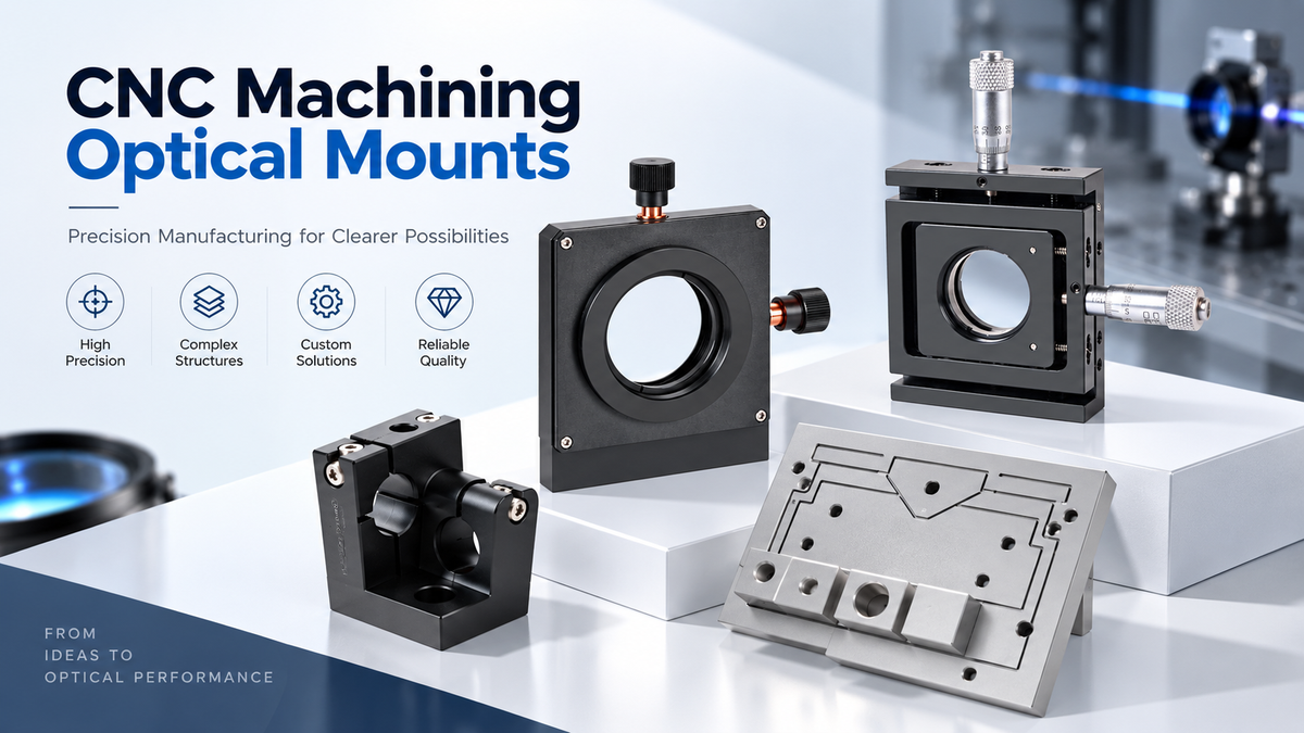
An optical mount can meet every dimension on the drawing and still cause alignment problems after assembly.
Common issues can include uneven mounting surfaces, hole position errors, tight fits after anodizing, and deformation in thin sections.
None of these problems looks dramatic on its own. In an optical system, however, a small mechanical shift can change the position or angle of a lens, mirror, sensor, or laser beam.
So CNC machining optical mounts requires more than simply producing a small metal bracket within tolerance. The machining process has to protect the relationships between critical features, maintain stable reference surfaces, and account for what happens after finishing and assembly.
XY-GLOBAL, as an expert in CNC machined optical parts with 15+ years of expertise, has produced numerous custom optical components for clients worldwide and received positive feedbacks. Read this blog post for the hands-on XY-GLOBAL has accumulated over the years and get to know the machining details that matter most, from datum control and material selection to thermal stability, surface treatment, inspection, and supplier selection.

What Does an Optical Mount Actually Need to Control?
An ordinary bracket mainly provides mechanical support, while an optical mount must hold and position lenses, mirrors, sensors, cameras, or other optical components with greater accuracy and repeatability. Optical mounts hold and position components such as lenses, mirrors, filters, sensors, prisms, cameras, and laser assemblies.
Some are fixed. Others provide angular or linear adjustment. Kinematic and flexure mounts may provide very fine pitch and yaw adjustment. Commercial optical mounts, for example, are commonly specified not only by optic size and material but also by adjustment range, screw pitch, and minimum controllable motion.
That tells us something important about manufacturing.
The mount is not there simply to support weight.
Its job is to maintain a predictable mechanical relationship between the optic and the rest of the system.
A typical custom mount may contain a precision bore for an optical element, a flat base that establishes the installed position, threaded holes for fastening, dowel holes for repeatable location, and slots for adjustment.
Each feature may be easy to machine by itself.
The challenge is keeping them correct relative to one another.

Common CNC Machined Optical Mounts
Different optical systems use different mounting structures.
| Mount Type | Typical Function | Machining Focus |
| Lens Mount | Holds And Centers A Lens | Bore Size, Concentricity, Seating Face |
| Mirror Mount | Positions A Reflective Optic | Flatness, Pivot Features, Angular Stability |
| Kinematic Mount | Provides Fine Adjustment | Pivot Geometry, Screw Interfaces, Repeatability |
| Sensor Or Camera Mount | Controls Sensor Position | Datum Face, Bore Position, Perpendicularity |
| Optical Base | Supports Multiple Components | Flatness, Hole Position, Thermal Stability |
| Laser Mount | Supports A Laser Module | Alignment, Heat Transfer, Rigidity |
| Optical Bracket | Connects Components Or Assemblies | Hole Pattern, Stiffness, Datum Relationships |
The exact tolerance does not need to be equally tight across every feature. What matters is identifying which surfaces and features control the final optical position.
Datum Control Is Central to Optical Mount Accuracy
A strong datum strategy is one of the most important parts of CNC machining optical mounts.
In many designs, the primary mounting surface becomes the natural reference for the rest of the part. Precision bores, locating holes, shoulders, and secondary mounting faces can then be controlled relative to that reference.
This keeps machining and inspection connected to the way the part will actually be used.
Problems often appear when the manufacturing reference does not match the assembly reference. A part may pass dimensional inspection but still require excessive adjustment during installation because the critical features were not controlled from the same functional datum.
The machining process should therefore reflect the assembly relationship.
If a lens bore determines optical position relative to a base surface, the machining setup and inspection plan should protect that relationship. If a pair of dowel holes establishes repeatable installation, their positional relationship to the optical feature becomes more important than many secondary dimensions.
This approach also helps avoid unnecessary over-tolerancing.
Instead of tightening every dimension, the most demanding tolerances can be concentrated on the features that actually affect optical alignment.
Flatness, Parallelism, and Perpendicularity
Optical mounts often rely on simple-looking surfaces that carry much more functional importance than their appearance suggests.
A base surface that is not sufficiently flat may rock during installation or deform when screws are tightened. A lens or sensor seat that is not properly aligned to the mounting surface can introduce angular error. Two parallel mounting surfaces may also need careful control when the part locates between multiple structures.
These geometric relationships often matter more than reducing a general dimensional tolerance from ±0.05 mm to ±0.01 mm.
Flatness is commonly important on mounting and seating surfaces. Perpendicularity becomes critical when a precision bore must remain normal to a base plane. Position tolerance is useful for locating dowel holes, mounting holes, and optical-axis features relative to a defined datum system.
For rotational features, runout or concentricity may be important where several cylindrical surfaces share a common axis.
The tolerance should follow the optical function.
A machine-vision camera bracket does not always need the same control as a high-stability laser mirror mount. Applying extreme tolerances everywhere usually adds machining and inspection cost without producing an equivalent improvement in system performance.

Material Selection for Optical Mounts
Aluminum is common in optomechanical systems because it is lightweight, easy to machine, and suitable for black anodizing.
It is not the only option. Material selection should consider the complete operating environment, including stiffness, temperature variation, weight, corrosion resistance, and the surrounding assembly.
| Material | Main Advantages | Main Considerations |
| Aluminum 6061-T6 | Lightweight, Good Machinability, Easy To Anodize | Relatively High Thermal Expansion |
| Aluminum 7075 | Higher Strength And Stiffness | Higher Cost, More Attention To Stress |
| Stainless Steel | High Rigidity, Wear Resistance, Corrosion Resistance | Higher Weight And Machining Cost |
| Titanium | High Strength-To-Weight Ratio | Expensive Material And Machining |
| Invar | Very Low Thermal Expansion | Heavy, Expensive, Difficult To Machine |
| Brass | Good Machinability And Dimensional Stability | Higher Density |
| Engineering Plastics | Lightweight, Insulating | Creep And Thermal Movement |
Aluminum 6061-T6
6061-T6 is a practical choice for many lens mounts, optical brackets, camera mounts, and general photonics hardware.
It machines cleanly, has good strength for its weight, and works well with anodizing. For laboratory equipment, machine vision, and general optical assemblies, it often provides a good balance between performance and cost.
Aluminum 7075
7075 provides higher strength and stiffness and can be useful for compact structures where the section cannot simply be made thicker.
The trade-off is higher material cost and, depending on the geometry, greater attention to residual stress and process planning.
Stainless Steel
Stainless steel is useful where rigidity, wear resistance, corrosion resistance, or thread durability is important.
It can also be a good choice for small precision parts where weight is less critical.
Invar
Invar is selected when dimensional stability over temperature is more important than weight or machining cost.
It is not necessary for most optical mounts, but it can make sense in metrology, interferometry, precision laser systems, and other thermally sensitive applications.
Thermal Stability and Optical Alignment
Temperature affects every metal component.
For optical hardware, the important issue is how that dimensional change influences alignment.
Aluminum expands more with temperature than stainless steel, titanium, or Invar. That does not automatically make aluminum a poor choice. In many systems, aluminum works very well because the surrounding frame and mount expand in a similar way.
Problems become more difficult when different materials expand at different rates.
A stainless steel component mounted to a large aluminum structure, for example, may behave differently as temperature changes. The design may still work perfectly, but the thermal relationship needs to be understood.
For this reason, material selection should consider the entire assembly rather than the optical mount in isolation.
The operating temperature range, optical path length, mount geometry, surrounding materials, and acceptable drift all influence the decision.
For thermally sensitive systems, the geometry itself can also help. Symmetrical structures generally behave more predictably than highly asymmetric ones. Shorter optical lever arms can reduce the effect of small dimensional changes.
Residual Stress and Machining Distortion
A part can change shape even after the cutting tool has finished its work.
This is especially common with aluminum parts that contain deep pockets, thin walls, or large amounts of material removal.
Machining releases internal stress. The part may also deflect under clamping force or cutting pressure.
When the fixture is released, a broad mounting surface can move slightly.
This is one reason optical mounts should not always be machined in a single aggressive sequence from raw stock to final tolerance.
For sensitive parts, a better process may include rough machining first, leaving stock on important surfaces, allowing the material to stabilize, and then completing the final finishing operations.
The exact sequence depends on the material and geometry.
A thick optical base and a small lens ring do not need the same stress-control strategy.
What matters is recognizing distortion risk early rather than discovering it after final inspection.
Thin Walls Need Special Attention
Compact optical assemblies often use thin walls and lightweight pockets to reduce mass.
This can be useful for moving stages, robot-mounted cameras, or systems where space is limited.
It also makes machining more difficult.
Thin sections can deflect under tool pressure. Large pockets can reduce stiffness during machining. Over-clamping can temporarily flatten a part that springs back after removal from the fixture.
Toolpath direction, cutting load, support, fixture design, roughing sequence, and final finishing passes all influence the result.
Sometimes a small design change can make a major difference.
A slightly thicker rib, a larger corner radius, or a more balanced pocket layout may improve machining stability without significantly increasing weight.
This is where early DFM becomes valuable.
When 5-Axis CNC Machining Helps
Many optical mounts can be produced successfully with 3-axis CNC machining.
Five-axis machining becomes useful when a component contains critical features on several faces, angled surfaces, deep access requirements, or complex optical interfaces.
The main benefit is not simply the ability to create unusual geometry.
Reducing the number of setups can also help maintain the relationship between features located on different faces.
Every re-clamping operation introduces another opportunity for setup variation.
For a complex custom optical mount, keeping several features in one coordinated machining setup can improve consistency and simplify datum transfer.
That does not mean every optical component should be moved to a 5-axis machine.
Process selection should follow the geometry.
A simple rectangular camera bracket may be more economical on a 3-axis machine, while an angled multi-face laser mount may benefit significantly from 5-axis machining.
Precision Bores and Optical Interfaces
Bores are common in optical mounts because they often locate lenses, bearings, bushings, laser modules, or cylindrical housings.
A precision bore has two jobs.
It must have the correct size, and it must be in the correct place.
Both matter.
A bore that is within diameter tolerance but offset from the mounting datum can still shift the optical axis. A correctly positioned bore that is too tight after anodizing can create assembly problems.
Depending on the requirement, the final bore may be produced by interpolation, precision boring, reaming, or a combination of machining operations.
The surrounding geometry should also be stable before the final bore is finished.
If a large pocket is machined after the bore is completed, stress release can change the relationship slightly.
For demanding optical parts, operation sequence therefore matters almost as much as the tool itself.
Threads, Dowel Holes, and Adjustment Features
Optical mounts often contain a mix of ordinary mounting holes and very functional small features.
Dowel holes are usually used for repeatable location. Their position and fit therefore deserve more attention than a normal clearance hole.
Adjustment threads can also be sensitive.
Fine-pitch screws used for optical adjustment need clean threads and good engagement. At the same time, excessively deep small threads can increase machining difficulty without providing useful additional strength.
Slots are common during development because they allow the optical assembly to be adjusted before the final position is confirmed.
Once the design is stable, some of those adjustment features can often be replaced with dowel holes, shoulders, or more defined locating geometry.
This improves repeatability and reduces the amount of adjustment needed during final assembly.
Vibration and Structural Stiffness
Optical alignment is affected not only by machining accuracy but also by how the mount behaves under load.
This matters in machine vision, robotics, automated inspection, LiDAR, mobile platforms, and equipment located near motors or high-speed mechanisms.
A long narrow bracket can flex.
A thin plate can vibrate.
A heavy camera mounted far from the base can create a large bending moment.
In these situations, reducing a dimensional tolerance may do very little to improve performance.
Structural changes are often more effective.
A shorter overhang, wider base, reinforcing rib, better support location, or improved clamping pattern can increase stiffness and reduce movement.
Locating pins can also improve repeatability after removal and reinstallation.
The best design balances machining accuracy with mechanical stability.
Inspection for CNC Machined Optical Mounts
Inspection should follow the function of the part.
A complete dimensional report is useful, but the most important measurements are usually the ones that confirm the optical and assembly relationships.
For example, a mounting base may establish Datum A. A precision bore can then be measured for position and perpendicularity relative to that surface. Dowel holes may be checked for position relative to the same datum structure.
This produces inspection data that reflects the way the part works in the final system.
| Feature | Typical Inspection Focus |
| Mounting Surface | Flatness |
| Optical Bore | Diameter, Position, Perpendicularity |
| Dowel Holes | Position And Fit |
| Lens Seat | Diameter, Flatness, Runout |
| Mounting Hole Pattern | Position |
| Multiple Reference Faces | Parallelism Or Perpendicularity |
| Finished Precision Features | Final Dimension After Coating |
CMM inspection is useful for complex positional and geometric requirements.
Bore gauges, gauge pins, height gauges, surface plates, and other inspection methods may also be more practical for certain features.
For some assemblies, functional inspection is also valuable.
A mount can be checked together with a mating component, gauge, or representative assembly to confirm that the dimensions translate into the expected fit and location.
Applications of CNC Machined Optical Mounts
Optical mounting hardware appears in a wide range of equipment.
Machine Vision
Camera mounts, lens brackets, sensor holders, and illumination structures need reliable positioning and good vibration resistance.
Laser and Photonics Systems
Mirror mounts, laser housings, optical bases, and beam-positioning components often require close control of datums and thermal behavior.
Medical Optical Equipment
Imaging systems, diagnostic devices, and optical modules may require small precision structures together with documented quality control.
Semiconductor Equipment
Optical inspection and metrology systems often use precision mechanical mounts to position cameras, sensors, lenses, and illumination components.
LiDAR and 3D Sensing
Weight, stiffness, thermal stability, and vibration resistance become important when optical components are installed on moving platforms.
Laboratory and Scientific Equipment
Custom lens mounts, mirror supports, translation structures, and optical bases often require flexible design and low-volume precision manufacturing.
How to Choose a CNC Machining Supplier for Optical Mounts
Selecting a supplier for optical hardware should involve more than comparing quoted tolerances.
A supplier may advertise ±0.005 mm machining capability, but that number alone does not show whether they understand the relationship between the optical bore, mounting face, dowel position, finishing allowance, and inspection datum.
The more useful capability is being able to turn functional requirements into a controlled process.
Datum and GD&T Understanding
The supplier should be able to identify how the part will be located during machining and how critical features will be measured relative to the final assembly datums.
This becomes especially important when several precision features appear on different faces.
Machining Strategy
Complex geometry may require 4-axis or 5-axis machining, but machine type alone is not enough.
A good machining plan considers setup count, distortion risk, finishing order, precision bore timing, and how much material is removed from each area.
Surface Treatment Control
For anodized optical mounts, the supplier should understand which interfaces can be coated and which may require masking.
Precision bores and close fits should be reviewed before the part reaches surface finishing.
Inspection Capability
CMM capability is useful when the part contains complex GD&T requirements.
The inspection strategy should also match the drawing datum structure.
The equipment matters, but the measurement plan matters just as much.
Prototype-to-Production Support
Optical systems often change during development.
A manufacturer that can support prototype machining, design feedback, finishing, inspection, and later production can reduce the need to rebuild the process when quantities increase.
Why Choose XY-GLOBAL for CNC Machining Optical Mounts
XY-GLOBAL provides custom CNC machining for optical mounts and optomechanical components, supporting projects from prototype development to repeat production.
Our manufacturing capabilities include 3-axis, 4-axis, and 5-axis CNC machining, CNC turning, precision grinding, EDM, surface finishing, inspection, and assembly support.
For complex optical components, 5-axis machining can help reduce setups and maintain feature relationships across multiple faces.
Our CNC machining capability can reach approximately ±0.005 mm depending on the part geometry, material, feature size, and inspection requirement. Measurement equipment includes CMM systems with measurement capability down to approximately 0.001 mm.
XY-GLOBAL operates under ISO 9001 and ISO 13485 quality systems.
For custom optical projects, we can work with aluminum, stainless steel, titanium, brass, and other engineering materials. Surface finishing can also be integrated into the manufacturing process, including anodizing and other application-specific treatments.
The goal is not only to machine the part to drawing.
For optical components, our engineering review can also consider the relationship between:
-
mounting surfaces,
-
precision bores,
-
locating features,
-
coating requirements,
-
thin-wall geometry,
-
assembly interfaces,
-
inspection datums.
This is especially useful during new product development.
A prototype may need more adjustment features to support optical testing. Once the layout is stable, the design can be reviewed again for production repeatability, assembly efficiency, and cost.
XY-GLOBAL can support this transition from initial custom prototype parts through EVT, DVT, PVT, and production manufacturing.
Final Thoughts
Reliable CNC machining optical mounts depends more on achieving a tight tolerance number.
The mount has to maintain the intended relationship between the optical component and the rest of the system after machining, finishing, and assembly.
That requires attention to datum structure, flatness, bore position, material stability, thermal behavior, structural stiffness, anodizing allowance, and inspection.
The most successful designs also separate critical optical features from ordinary mechanical geometry.
Precision is then applied where it creates a real performance benefit.
For a custom lens mount, mirror mount, camera bracket, optical base, laser mount, or other optomechanical component, involving the machining supplier early can make it easier to balance accuracy, manufacturability, and cost before the design reaches production.
FAQs for CNC Machining Optical Mounts
1. Can you machine optical mounts from customer-supplied CAD files?
Yes. STEP, STP, IGES, X_T, and other common 3D formats can be used for manufacturing review. For precision optical mounts, a 2D drawing is also recommended because it clearly defines datums, GD&T, critical dimensions, coating requirements, and inspection expectations.
2. Can you produce low-volume optical mount prototypes before mass production?
Yes. Prototype quantities are common for optical hardware, especially during alignment testing and system validation. Small batches can be produced first, then the design and machining process can be adjusted before moving into repeat production.
3. Can optical mounts be supplied with inspection reports?
Yes. Depending on the project, inspection documentation can include dimensional reports, CMM reports, FAI, material certificates, and surface treatment records. The inspection scope should ideally be confirmed before production so the required critical features are measured from the correct datums.
4. Can multiple optical mount components be machined and assembled as one subassembly?
Yes. For projects involving several related parts, machining, surface finishing, inspection, and assembly can be managed together. This can be useful for camera modules, lens assemblies, laser structures, and other optomechanical systems where mating relationships are important.
5. What is the typical lead time for custom cnc machined optical mounts?
Lead time depends on part complexity, material, tolerance, surface treatment, inspection requirements, and order quantity. Simple prototypes can often be completed faster, while complex multi-axis parts, tight GD&T, anodizing, or full CMM inspection may require additional time. For urgent projects, the schedule can usually be reviewed during quotation so the machining and finishing process can be planned around the required delivery date.
6. Is there an MOQ for custom optical mounts?
We support flexible order quantities for custom optical mounts, from prototype quantities and small batches to repeat production. There is no need to start with a large-volume order. Customers can validate fit, alignment, and assembly with a small quantity first, then increase volume after the design and process are confirmed.


Share:
Die Casting Manufacturers for Custom Aluminum and Zinc Parts